Engineering HomeWelcome to my web page. I created this site with the purpose of documenting my experienceses, post online applications (check the Design Tools section) and presenting engineering projects. Like most individuals, who grew up to become engineers, I enjoy taking things apart to learn and see exactly what make them work. I find that these kind of activities stimulate new ideas for improvement and even creation of new products. The constant advances in 3D modeling, Finite Element Analysis, System simulation softwares and 3D printing technology it is much faster and easier than ever to convert ideas into real objects in very little time. I intent to update this site often so you are welcome to visit often. I hope you enjoy the content. | ||
|
This video demonstrate how SolidWorks - Gearmates can also simulate pulley and cable mates in a assembly. | ||
Hydraulic ManipulatorHydraulic manipulators pack more energy density than DC motor driven manipulators. The rotary actuators in this design must be made from cast and machined aluminum in order to incorporate the intricate hydraulic passages required [1]. I wanted to design an arm with actuators with dimensions as close to a human arm as possible. I also wanted to minimize the profile of hydraulic hoses and pipes protruding out of the links. This configuration would help avoid snagging or rupturing during operation. What you see here in the picture is version 3. I have new ideas for version 4 and will post those pictures/documents at a later date. The challenge here is to transmit hydraulic pressure through each link while maximizing rotational range of movement. I plan to combine two technologies used in the material handling and wind energy industry. BOM | GD&T | FEA | Manual/Brochure | ||
|
This is a very good reminder of the capabilities of our standard bolts. Let's keep in mind its limitations as we go about designing machines, specially those that operate near people. | ||
Geometric Dimensioning & Tolerance ChartI keep this chart up to date with the latest ASME Y14.5 Standard. I use GD&T on a daily bases to design machines that portion food products at an industrial scale. A combination of HTML and Javascript, the page is interactive. Illustrations of usage are displayed or hidden by clicking the links attached to the names of each geometric control. You may access the page by clicking the link above. | ||
Thermal Expansion Fit Tool This Javascript tool can be used to determine possible changes in fit between parts subjected to thermal processes. Designers must make provisions to prevent assemblies that operate under temperatures gradients from jamming or ceasing up. The link above will open the tool and allow you to change the parameters that match your particular case. | ||
Fiber Optic Laser Focus MechanismIn this post I present a 3-axis focusing mechanism. This type of device is integral to the operation of cutting heads, welding heads and safety switches that utilize solid state laser energy. I worked on this mechanism trying to improve the accuracy, stability and strength of the mechanical adjustments. For example, one of the requirements called for the ability to displace the collimating lens at fine increments per screw revolution along a 4 mm span in all 3-axis. After managing to find a machine shop capable of producing a 0.1 mm pitch screw the next problem became obvious very quickly. The threads were not strong enough to tolerate the forces generated during the calibration process. Basically, if the user slipped while turning the screw the threads would be ruined. We disassembled and studied older versions of the device to learn and improve upon them. At a later date I'll post more part drawings showing tolerance requirements as well as a summary of techniques and mechanisms used in the fiber laser industry. In the mean time you can access BOM drawings clicking the title link. | ||
Appliance Benchmark StudyIn this post I will slowly disassemble a household vacuum cleaner. This project will give me the chance to measure and record the different fits and allowances used by the manufacturer to ensure their product would assemble and function correctly. I'll make note of some of the most interesting mechanisms and techniques used by the manufacturer. The electrical circuitry will also be considered. The report ends with a comparison of features found in similar vacuums out in the market. Click the link above to see the report. | ||
3D Modeling of Plastic ProductsThis Slide show demonstrate some of my experience designing plastic parts and devices with Solidworks and PTC Creo 2.0. In general the use of surfaces and 3D sketches constitute the bases of creating ergonomic shapes. Highly complicated shapes require the use of many reference geometries such as planes, axis, points, projected sketches, etc. In many instances the combination of several techniques is require to create one single feature. | ||
Pressure Vessel Analysis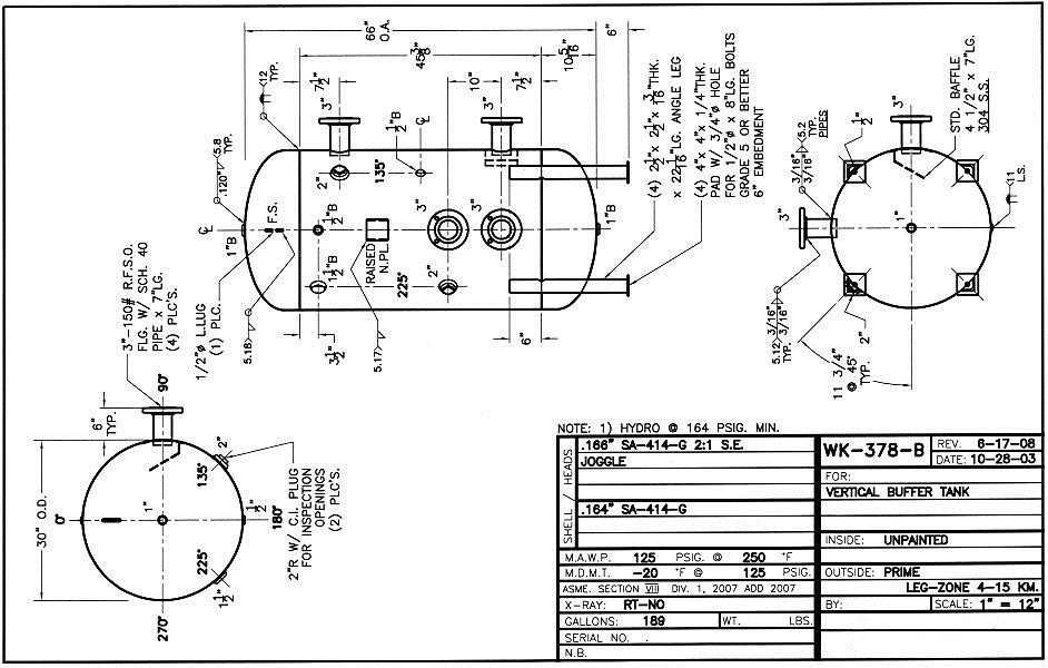 For this project I recreated a Vertical Buffer Hot Water Tank from a drawing that was available on-line. With this model I proceeded to perform a few FEA and CFD simulations: Static test, Pressure test, Vibration mode test, and Wind force stress test. The SW Simulation suite has these and several other tools to perform these tests. The results show that care must be given to the design of the support connections or welds around the legs. The drawing should have specified the placement of pads between the legs and the shell body. The pads can prevent the development of stress concentration points during thermal expansion. An experienced technician should be capable of joining the two parts with a strong weld pattern. BOM | GD&T | FEA | Manual/Brochure |
||
4-DOF Manipulator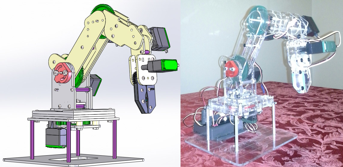 I originally created this manipulator for a graduate school project. The parts are made of laser-cut acrylic material [3] [4]. Most of the parts and hardware are commercially available from VEX but I had to design and build the base and links that make up the arm. It was the first time I had the opportunity to learn how to program controllers [6]. The arm can perform a pick-and-place operation by simply entering the locations A and B in x,y,z coordinates. The functions driving the motors compare the inputs from the user with the current position of the potentiometer sensors located at each joint. Using this feedback the controller makes the necessary adjustments. The Language used to write the program was C. BOM | GD&T | FEA | Manual/Brochure | ||
Rapid Prototype RepairThe Arm-Rest compartment in my vehicle broke. The hinges cracked at the pivot point and the compartment sat precariously on the console. An attempt at using Krazy® Glue did not work. I then decided to design a new part and incorporate a few changes to improve the original design. I found that a Nylon based filament was the ideal material for 3D prototyping, however the local MakerBot store didn't have that material available. Instead, I used their PLA filament (NatureWorks® Ingeo™ 4043D) which appears to have the strength to endure the repeated stresses of opening and closing the compartment. I am very satisfied with the final result and will probably use this material again in the future. BOM | GD&T | FEA | Manual/Brochure | ||
Electronics Test Module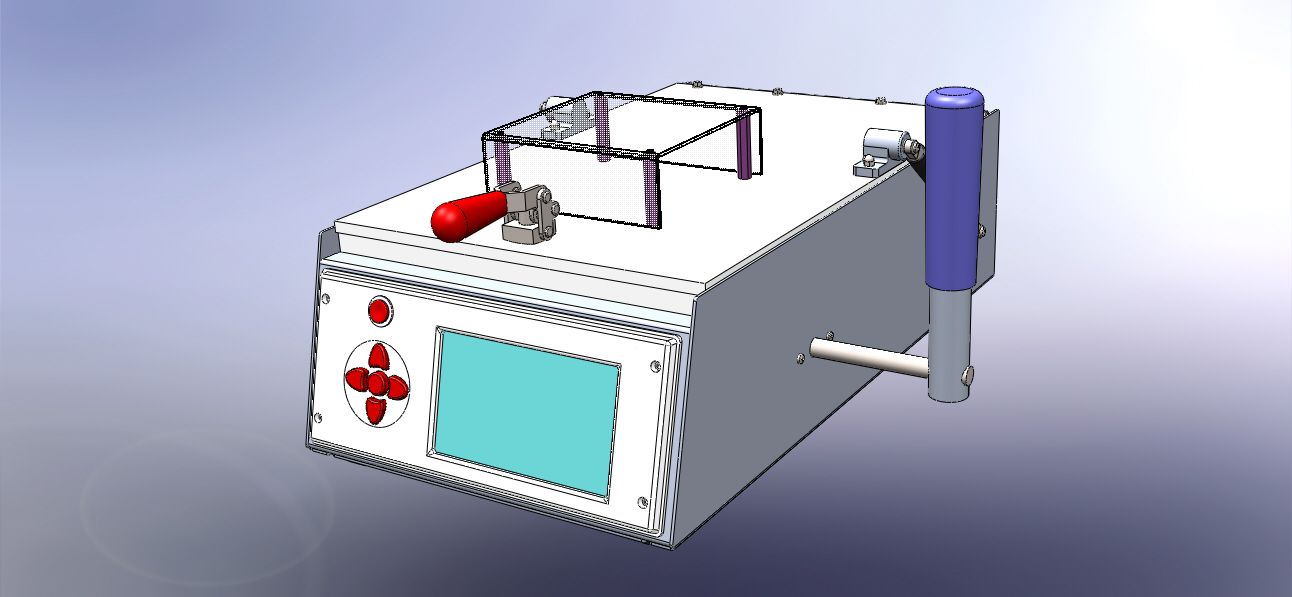 This ETM represents a typical low/mid scale production fixture used to test printed circuit boards (PCB) at the final stage of production [6]. The operator can confirm that the circuits work as intended by quickly connecting power and running programmed scripts which test every functionality of the product. Here, mechanical fixtures and solid-state electronics work together to provide more precise control over production lines. When designing test modules it is important to come up with fast, efficient mechanisms that (1) fix/release the PCB in place and then (2) engage/disengage the probes and electrical connectors. Some of these mechanisms include the use of cams, swash plates, ratchets, and bar linkages. Here, the module's housing parts are made of gauge 16 stainless sheet metal [2] and High-density polyethylene (HDPE) plates. The video includes a Computational Fluids Dynamics (CFD) simulation [7] in which the optimal air flow is determined to maintain the internal components at a stable temperature. BOM | GD&T | FEA | Manual/Brochure | ||
Microscope BenchmarkingI took an old Microscope and disassembled its components to the smallest screw. The idea here is to show the mechanisms that make image adjustments possible. In the Slide show I also highlight the assembly methods used to put the apparatus together as a final product. Last update 11/17/14. | ||
Reading Lamp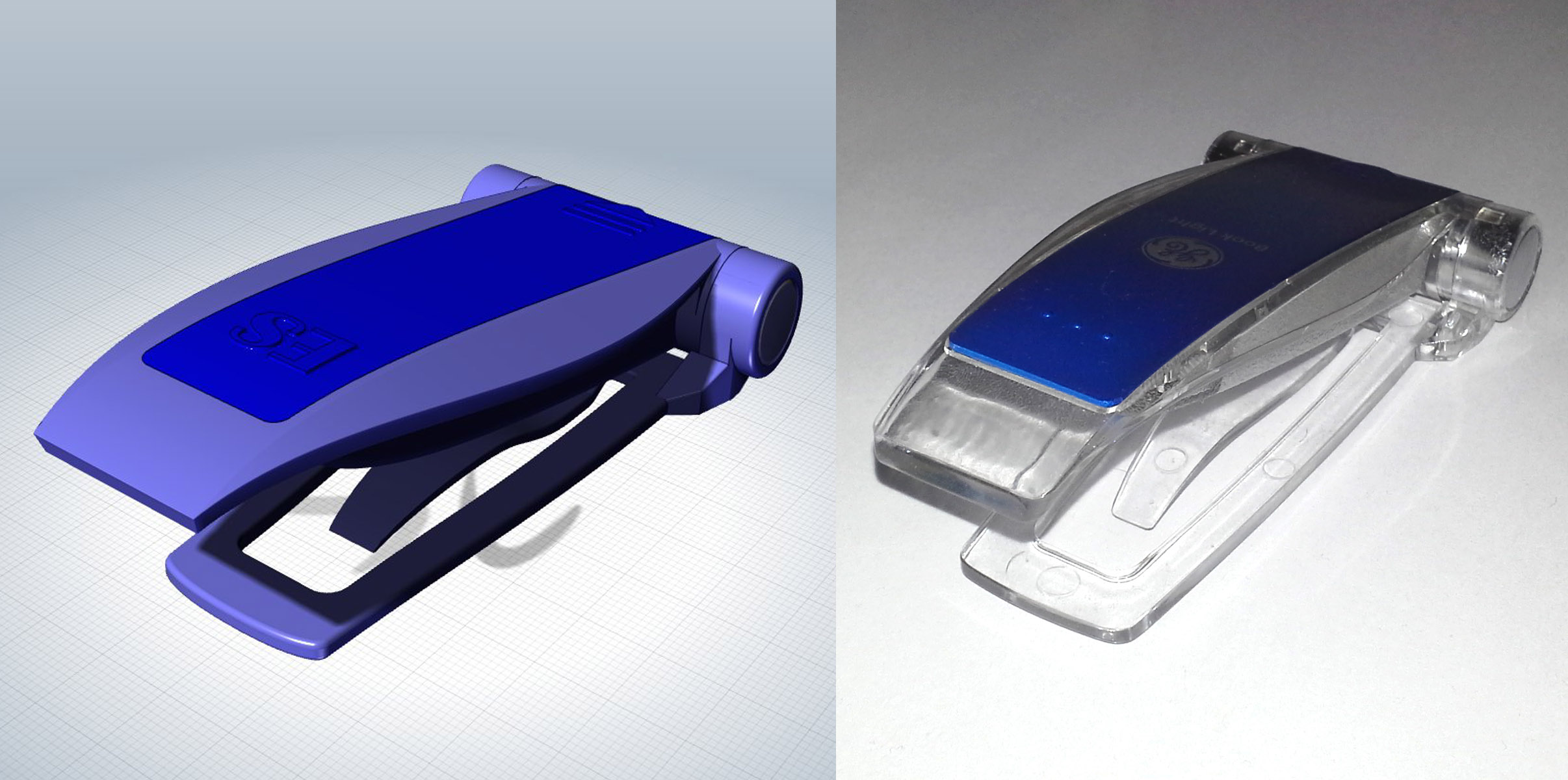 This project was intended to help me practice the creation of solid models using surfaces, splines and 3D sketches [7]. In the past I was more familiar creating objects made by machining, cutting, welding and a few with sheet metal. Consumer products, however, are mostly made out of plastics through injection moulding [4]. Here designs become more complicated because these objects need to be ergonomic in shape and also must be easy to extricate out of the mold by giving them draft angles, meaning that there are very few parallel surfaces. BOM | GD&T | FEA | Manual/Brochure |