VACUUM DESIGN PARAMETERSTypical Fits and DimensionsThe wall thickness in this vacuum varies between 0.0541 and 0.1716 inches. The plastic is thin at the handle areas and thick around the housing containing the brush and its motor assemblies. There are two motors in this vacuum: one powers the brush, the other drives the air-flow fan. Some particular areas worth highlighting are: the dust canister wall is 0.0748 - 0.0954 inch thick, the hinge tabs are 0.1119 - 0.1654 inch thick, the hose handle is 0.0885 - 0.1275 inch thick, and the vacuum motor housing is 0.0782 - 0.1183 inch thick. Figure 1 shows the measured fits found in the cylindrical and parallel matting parts. 
Assembly Features, Mechanisms and TechniquesThe hoses are attached by driving the
hose-end into special threads formed in the ABS plastic (Fig. 2A). Those threads are impregnated with an adhesive, which solidify and lock the hose in place. This glue
however was easy to remove; a stronger adhesive was used to secure the access cover for the power switches near the handle.
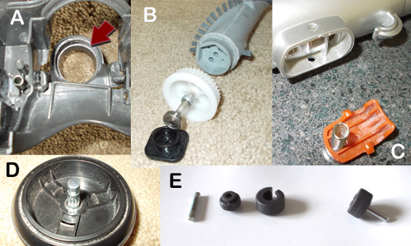
This machine featured several plastic parts that had rubber lining molded over them. The rear and front casters, are a good example, the rubber was formed around the plastic bearing (Fig. 2D-2E). The bearing had holes around the rim which effectively help lock the rubber to the bearing housing preventing separation. The only way to separate the rubber is cutting it with a sharp tool. Hose-end connectors also had rubber linings to create air tight seals. These molding technique can be done in a secondary process or simultaneously with the forming of the plastic part. 
The Electric CircuitryThe vacuum is designed to work with 120 Volts, 60 Hz energy supply. Consumes 700 W of power and draws a 6 Amp current for two brushed motors and six LED (Light Emitting Diodes). In Fig. 4 we can see that each motor can be activated independently. The rolling brush can be turned off while the hose is being used for dust suctioning. An electric schematic of the PCB will be posted shortly. 
ConclusionThis vacuum has lights intended to illuminate the work path which is particularly useful when working under furniture. However few users would be willing to bend under furniture with the vacuum to take advantage of these lights. The vacuum allows the user to power the brush independently from the air-flow motor, which is a good idea given the fact that the brush and the motor are connected by timing belts and pulleys. Because the of the toothed profile of these parts the motor is subjected to high wear due to jamming and stall torque. Other vacuums use plain-profile belts which simply slip over the pulleys when jamming occurs. The rotating brush does not have a height adjustment mechanism, which limits the types of carpets the device can be used on. Competing devices use a vertical cam to provide adjustment. |
| Copyright © 2015 Estiven R. Sierra |