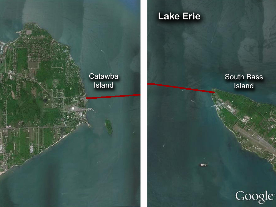
This project connected South Bass island to high voltage generation
from Catawba, approximately 3 miles away. I was brought into this project as a way of introduction to the way Kerite Cable Services (KCS) approach project management.
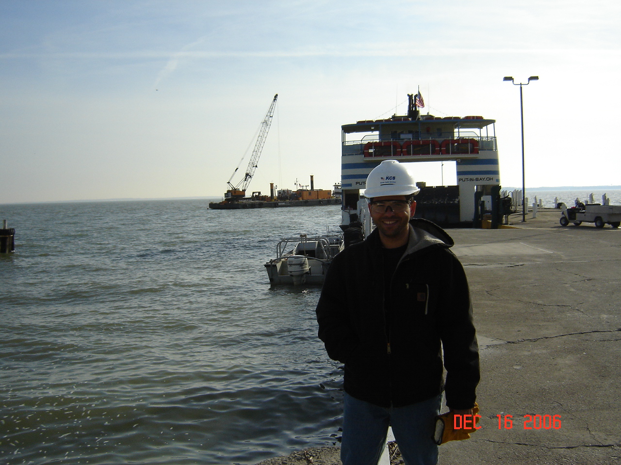
I observed and learned about the challenges related to underwater installations during the winter months. Watching the work from the
deck of the barge was brutal due the the frigid temperatures of Lake Erie. Only one small room in the barge was heated. Ironically the
two divers working underwater enjoyed far more comfortable working conditions due to their water-heated dive suits. The barge can be seen in Fig. 2
distinguishable by the giant crane boom. Right in front of it is the Put-in-Bay ferry which carries passengers and vehicles into and from South Bass Island.
Figure 2- Cable laying barge and the Put-In-Bay ferry.
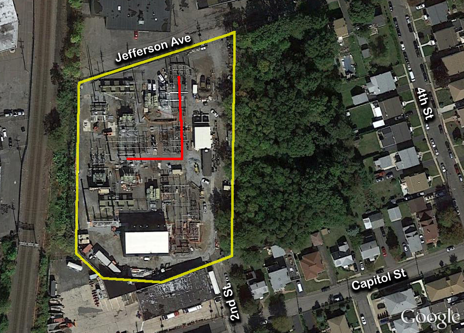
138 kV Underground Installation Egg Harbor, NJ
Figure 1- Three-phase circuit installation.
The Cardiff-Lewis project was the first project in which I was fully engaged from the
very beginning to its successful end. It took several months of negotiations and budget planning but, in the end, we were awarded the contract
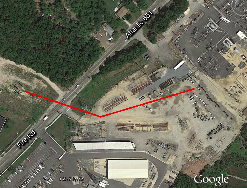
to begin construction in February 2007. The first mayor feature of this 1.1 Million project consisted on the construction of a 273 yard long duct bank (fig. 2)
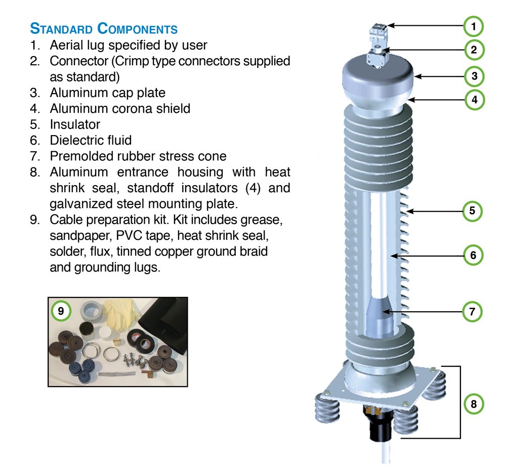
which would protect the underground (UG) 138 kV circuit. The electric circuit consisted of stranded copper conductors; each terminating high above
ground into a G&W PAT140 terminator (fig. 3). Each terminator then connected to the overhead circuit.
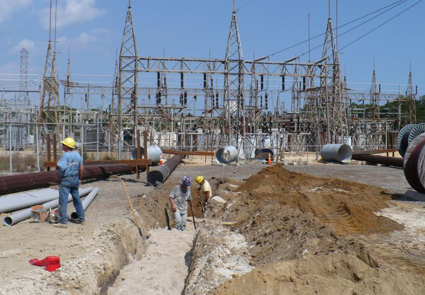
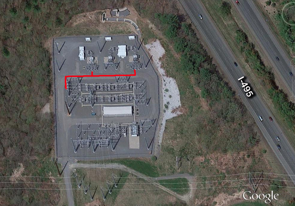
Figure 2- Duct bank construction at the substation end.
Because this station delivered electricity to a large population of NJ, each UG phase consisted of two cables; one for continuous service and a second one to serve as an emergency spare.
Therefore, a total of six (6) cables would have to be pulled in to position; along with one termination on each end. The duct bank route is shown in figure 1. Figure 2 shows the
construction of the 3x2 duct bank at the substation. The steel structures to be erected there can be seen laying on the ground. The PVC ducts were encased in concrete and plenty of warning
tape was buried along the length of the installation.
Figure 3- The G&W PAT140 Terminator.
A typical Kerite UG cable is made of a 2000 kcmil CU conductor, which is surrounded by Non-conducting Permashield® Stress Control Layer.
This in turn is surrounded by a layer of Discharge Resistant EPR™, a semi-conducting layer, concentric CU wires for electric shielding, and a polyethylene
jacket for mechanical protection. More details with regards to cable construction can found in Kerite's website. Each cable was pulled through the duct bank with a powerful winch. Along the process I paid close attention
to tension forces, which were constantly transmitted via wireless from an in-line sensor attached to the cable and into a portable, hand-held device. I was supposed to signal the winch operator
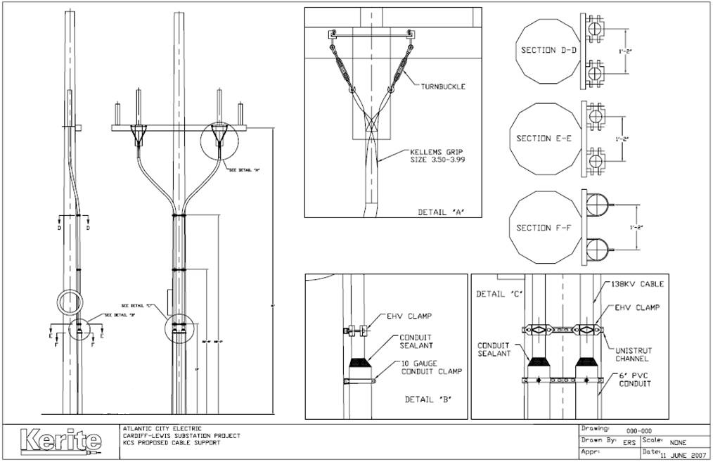
in case any unusual spikes in force was detected. Figure 4 shows instruction blue prints I created to illustrate the placement of hardware intended to support the cable vertically along the steel poles.
Figure 4- Cable support plans.
The duct bank ended at the Right-of-Way across Fire Road as shown in figure 5.
We arranged to have local law enforcement help control traffic while construction moved across the two-lane road. I spent weeks at a time
supervising the project, all the while driving back and forth between NJ and CT and planning ahead for other upcoming projects.
The project finally ended on November of 2007 after successfully testing the circuit.
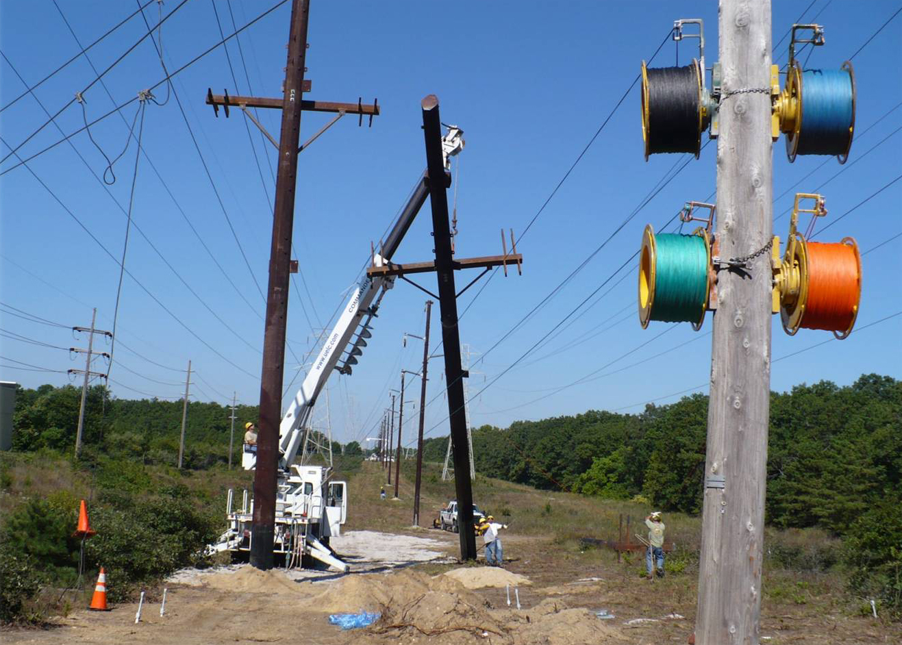
Figure 5- Erecting HV structures at Right-of-Way end.
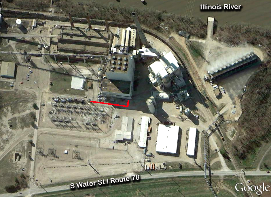
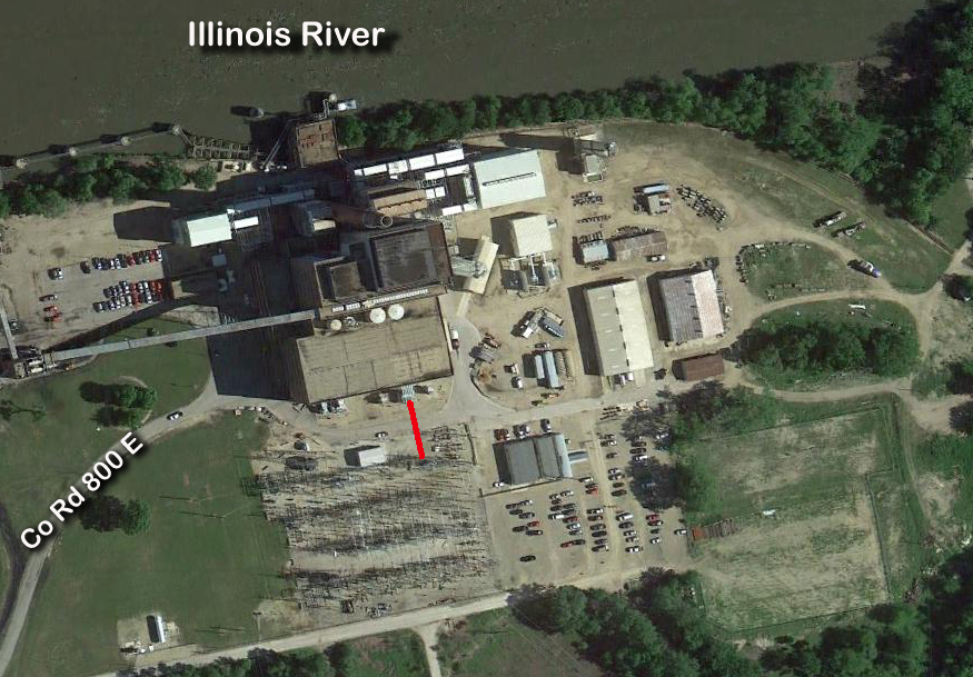
138 kV Underground Installation Havana, IL
Figure 1- Cable Laying Route.
From July through August 2007 I was involved in this installation, which needed
a short 95 yards connection between switching structures. The tasks were typical of other such projects: cable installation, termination, shield testing, etc.
This being another remote location, I invested many hours planning the schedule of operations in order to minimize loss time. Delays were always
guarantee to occur in every project, so I applied lessons from previous projects and implemented measures such as: carrying our own mini-hardware supply,
buy extra fuel for the portable generator, bring our own work lights, double the amount of consumables, etc. I also kept the technicians feed throughout the day
by bringing take-out meals to the work site.
Thankfully we live in a time were planning tools abound. The most common tools we used at Kerite included Excel,
Microsoft Outlook, MS Project, Word, PowerPoint, Portable cellphones, GPS technology, and portable cameras. MS Project was of great help when it came to keeping
track of parts ordered, who was in charges of what task and when they were supposed to perform them, what and when documents needed to be signed. The ability to
track mounting costs against the set budget was also a great advantage. I particularly preferred viewing the overall project via the Gantt Chart interface.
69 kV Underground Installation Fargo, ND
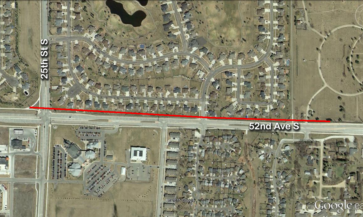
Figure 1- Cable laying route.
In November of 2007 I was given charge of the Ponderosa-Saunders 69 KV project. It consisted in the installation of
three (3) underground cables across a residential neighborhood. The developer wanted to increase property value around their project by keeping
the immediate view of the sky clear from overhead lines (Fig. 1). This project was particularly difficult due to the ND winter weather and the fact
that I was brought into it when it was already well under way. I had to become acquainted with all the details of its execution very quickly in order
to tackle the mounting amount of issues. Including a Manhole that kept filling up with water.
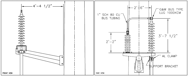
Figure 2- Cable termination.
This project gave me a chance to be a Mechanical Engineer again, at least for a small part of it.
I was obliged to modify the existing support arm for the cable terminations. The previous engineer had arms made to support the rigid type terminators, such as the PAT140 model.
However, we ended up purchasing flexible type terminators. Flexible terminators are supposed to hang from the end of the conductor as opposed to clamped from below.
After some brainstorming sessions I came up with the idea depicted in figure 2. Using the short rigid standoff sitting parallel to the terminator
I placed a schedule 80 CU bus tube bended 90° to offer cantilever support. Calculations showed that the tube had enough stiffness to support the weight of the cable
as well as wind gusts common of the ND plains.
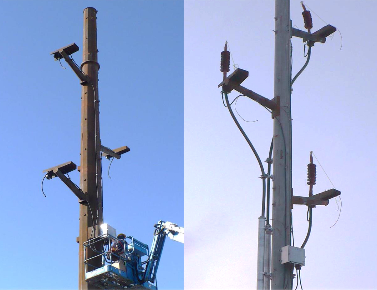
Figure 3- Flexible Terminators at each end of the installation.
Figure 3 shows the modified support arms during installation. I moved on to another project by March 2008 before the terminations were installed
and tested so I was unable to see the finished result. However, the final installation can be seen by visiting the area through Google maps or any other street-viewer browser.
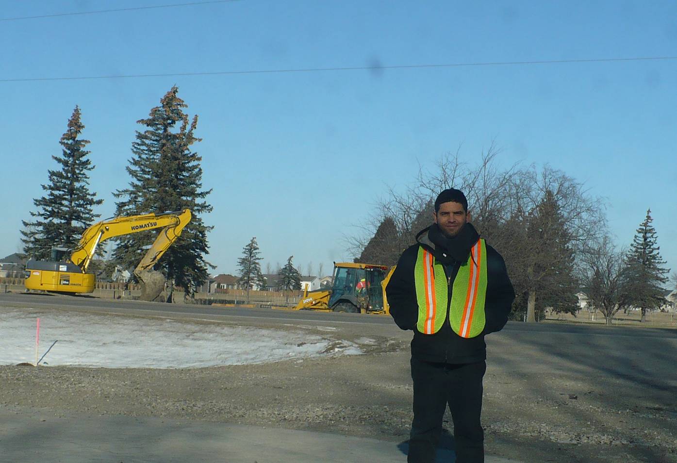
Figure 4- Adjusting to the ND winter cold.
The winter weather in Fargo was interesting; there were days with temperatures in the teens, which we could deal with easy enough (Fig. 4). However, other days
temperatures hovered above freezing long enough to create very muddy conditions. The mud would get into our boots, clothes, tools, and vehicles making for very exhausting and slow work days.
Yet, those conditions were preferable to rain or snow storms. Heavy rain or snow conditions could seriously affect the profitability of a project due to work delays and increased labor costs.
138 kV Underground Installation Saddle Brook, NJ
Figure 1- Cable Laying Route.
From January through April 2008 I was involved in this installation, which needed
a short 75 yards connection between switching structures. The tasks were typical of other such projects: cable installation, termination, shield testing, etc.
Safety was a very important aspect of everyday activities, especially when working in small and crowded substations like this one. Safety procedures were reviewed every morning
before starting any of the scissor lifts or boom vehicles. Every individual operating such vehicles was required to wear fall protection, along with other
required personal protection equipment (PPE). Every lifting operation required a sporter and two-way communication. I was required to maintain CPR certification and also kept a
defibrillator device in the vehicle in case of emergencies. Fortunately, during my tenure at Kerite we never had to deal with anything beyond minor cuts, bruises and deflated egos.
138 kV Underground Installation Hennepin, IL
Figure 1- Cable Laying Route.
From February through August 2008 I was involved in this installation, which needed
a short 34 yards connection between switching structures. The tasks were typical of other such projects: cable installation, termination, shield testing, etc.
Short underground installations are very common in generation plants and switching stations. They are on average three (3) times more expensive than installing
overhead lines. Because overhead lines are required to maintain a minimum amount of clearance between each phase and the ground, they eventually run out of space
as demand for more infrastructures grow. It is this market the Kerite Company tries to reach year after year.
The main difficulties in planning for the Hennepin project included (1) coordinate delivery of parts to this remote section of Illinois,
(2) anticipating what tools, hardware and small parts we might need to bring with us because the closest hardware store was some two hours away,
(3) finding adequate places to eat and stay, and (4) planning how to handle emergency situations while responders arrive from the nearest city.
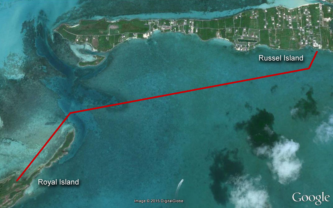
Underwater Project Russel Island, Bahamas
Figure 1- Cable Laying Route.
The project would transfer electricity from Russel Island 3.2 miles to the closest
point at Royal Island (Fig. 1). Royal island was slated to be developed into a vacation resort with hotels and golf courses.
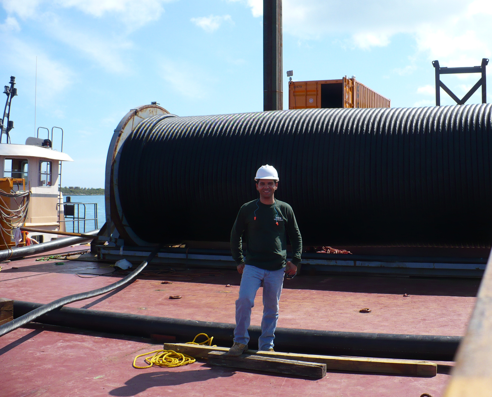
Because the amount of cable we could store in the reel was limited (Fig. 2), the laying operation was divided in two. Each cable was laid starting from each end destination
and left floating at a specific coordinate between the islands. A splicing box was then used to join both ends and complete the circuit.
Figure 2- Cable Reel.
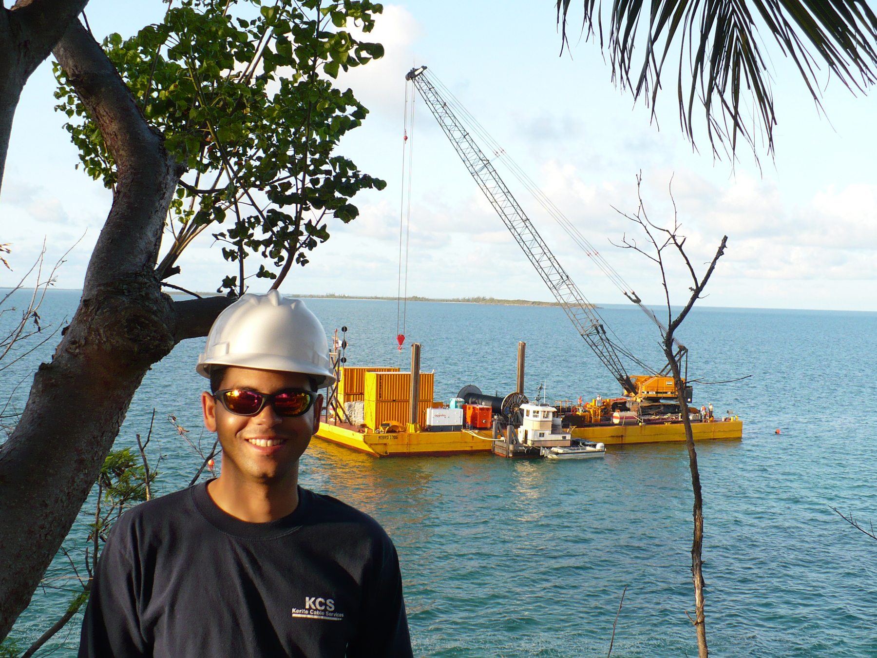
The contractor's barge is shown in figure 3. The barge is driven by tugboats and
anchored by vertical hydraulic pylons which can be lowered into position when the correct coordinates are reached. In the picture you can also
see the high speed boat, AC diesel powered generator, weather tower, and giant crane to handle the cable reel.
Figure 3- Shallow Water Barge.
For underwater projects the bulk of responsibility for day-to-day operations rested with the contractor
laying down the cable. The purpose of my presence was to be a witness and liaison between the two companies. Watching these professionals at work was a real treat.
I learned many of the intricacies and challenges involved in underwater high voltage installations at the hands of people of great experience and talent, and for that
I am very grateful.
138 kV Underground Installation West Amesbury, MA
Figure 1- Cable Laying Route.
I was involved in this installation from May through July 2009. This was a new construction and the civil
engineer decided to put two (2) UG circuits before any overhead lines were installed; in anticipation of the future energy needs of the area. The tasks were typical of other such projects: cable installation,
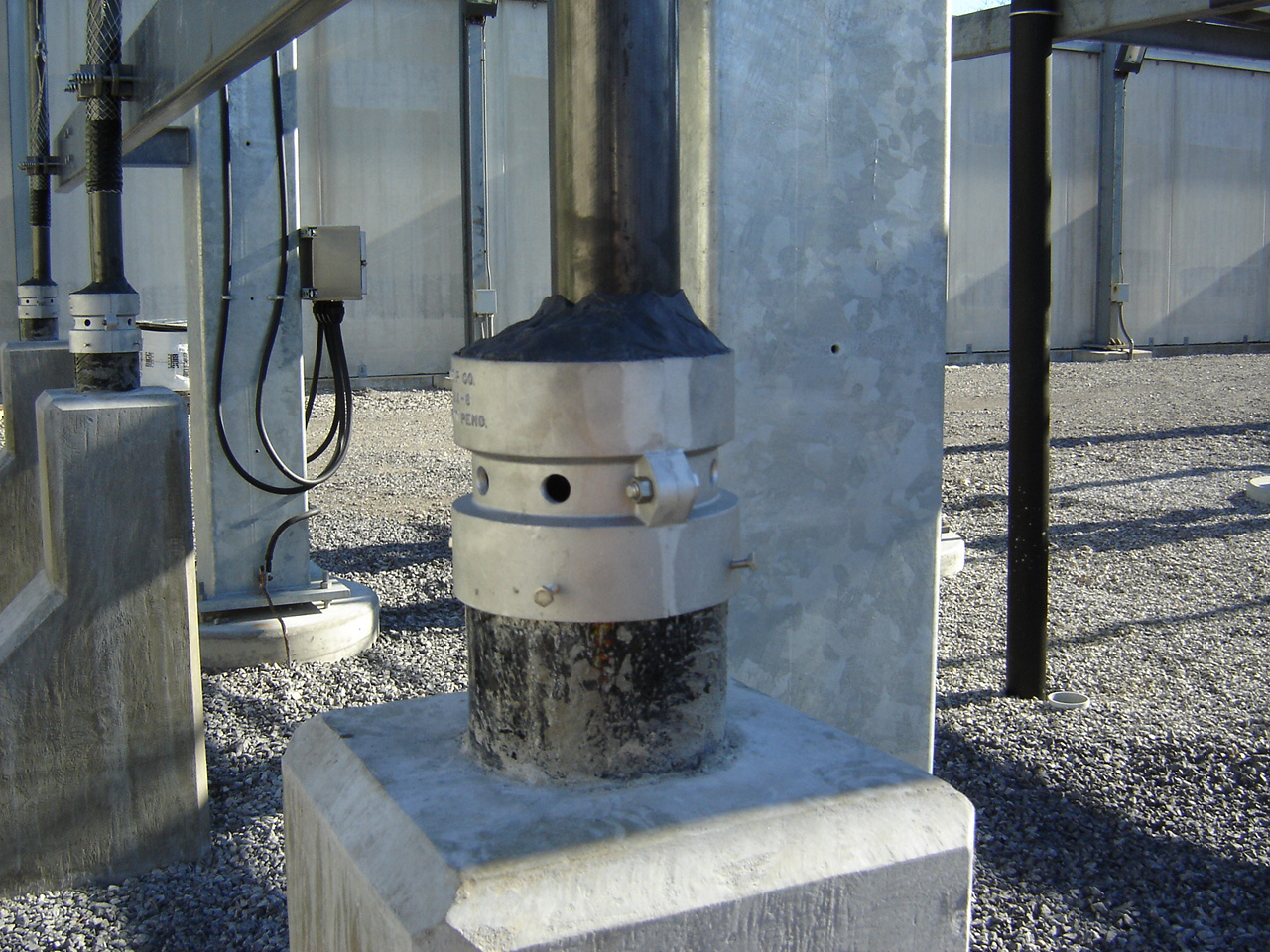
termination, shield testing, etc. The weather was rainy most of the time, the water and mud was everywhere and the work had to be halted several times. Underground cables contained in PVC pipes
do collect some water every time it rains. However, this water eventually evaporate due to the fact that the cable becomes hot during normal operation. Each PVC
opening is fitted with venting cap such as those shown in Fig. 2 that allow humidity to escape.