Mechanical Design Engineer at IPG PhotonicsBack to Resume |
|
Fiber-to-Fiber Optic Switch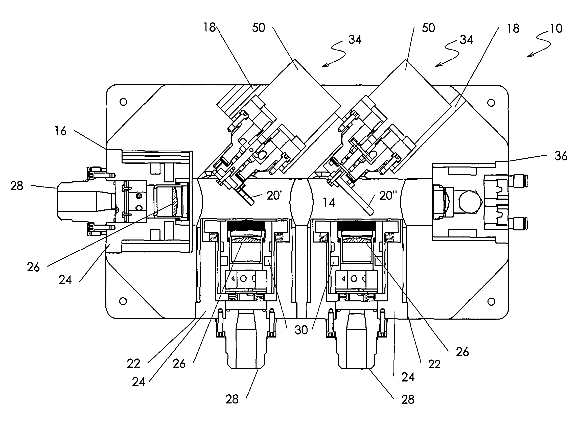
During my time at IPG I had the pleasure to work on the testing and development of the Fiber-to-Fiber Optic Switch and Coupling units. These devices are popular because they allow one single Laser unit to serve several work-cells through computer controlled mirrors and lenses. They also provide stray energy monitoring, ease of maintenance and easy work-cell reconfiguration. These devices were meant to compete directly with those developed by Optoskand and TeraDiode. I was involved mostly in the assembly and testing of the devices. The result of these activities provided valuable insight on how to combine Quartz, metal and high energy light to create a reliable Laser delivery system. You can read more about the workings of the switch in its Google patent page and IPG's website. 
Feature goals: XYZ Focus and Interlock MechanismThe Input and Output focus of the device was meant to be set at the lab. so it would be ready to use upon delivery. The mechanism consisted of two (2) 90° spring-loaded, wedge-joint, screw-driven rings which provided adjustment in the X,Y plane. These parts are marked by numbers 5, 6, 9, 10, 11, 14, and 17 in figure 3. The Z-axis adjustment consisted of a spring-loaded, pivot-joint, screw-driven lever that pushed the Collimating lens housing in and out along the focus axis. Part numbers 2, 3, 4, 7, 8, 12, 15 and 18 (Fig. 3) comprise most of the Z-axis focus mechanism. The X,Y displacement was 4 mm in each axis, the Z-axis had a 6 mm displacement. 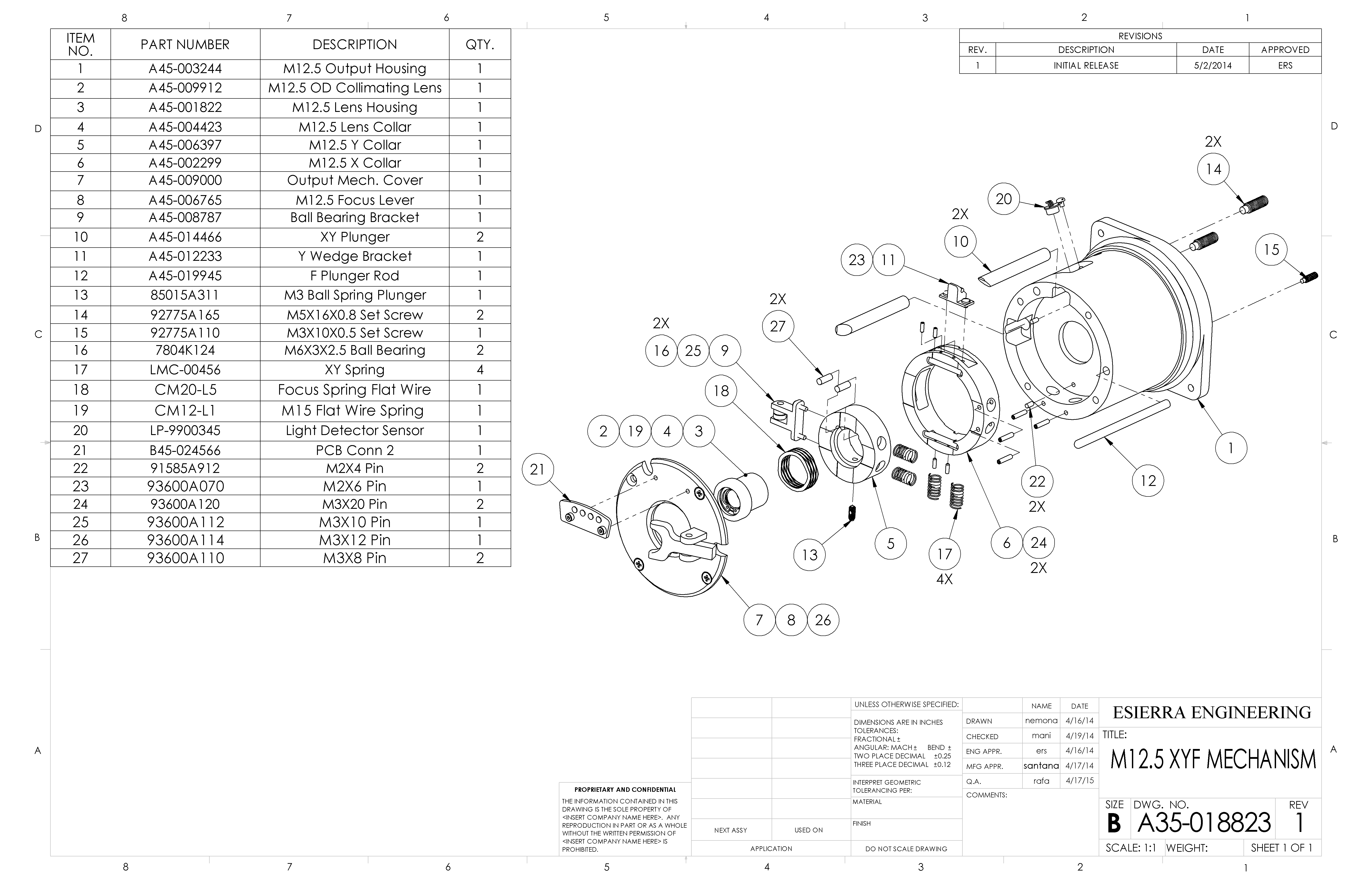
The bayonet interlock mechanism, shown in figure 4, secures the fiber laser bayonet to the focusing mechanism. Three steel pins are rotated until the bayonet is lodged into a funnel-shaped seat that effectively locks it and prevent movement in all degrees of freedom (Fig. 4 parts 1-5). 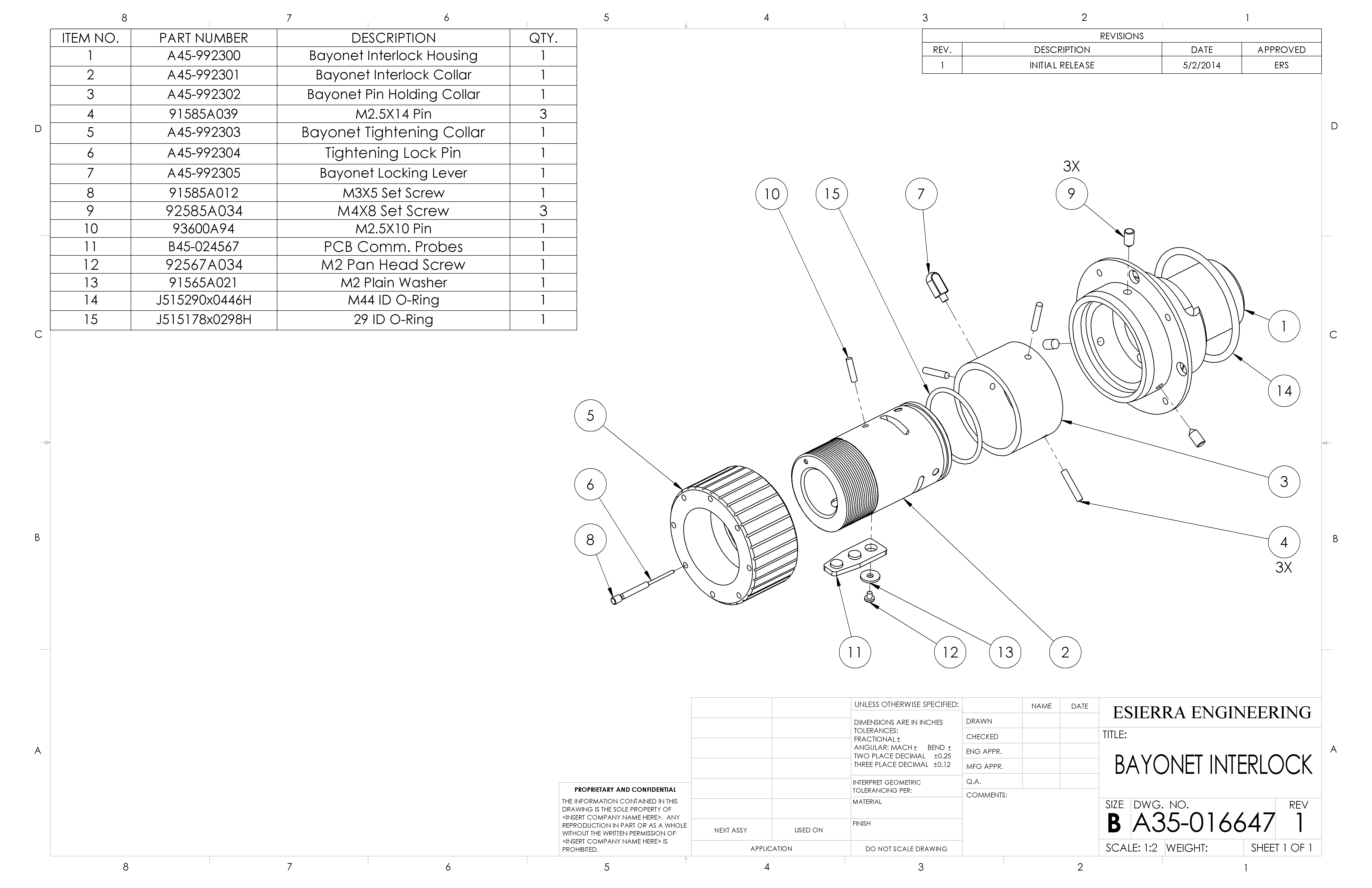
Design Changes & ImprovementsThanks to the availability of software design tools, engineers with little or no training in optics
like myself, can successfully design and create laser assemblies. Many of these tools are offered free on-line, such as OSLO,
WinLens3D and Edraw Max.

Taking some elements from other optical machines I developed a slightly different housing assembly that minimize shifting by incorporating yet another spring element. Figure 5 shows the lens housing sitting on two pins that acted as rails along the Z-axis and a spring-loaded plunger. All three support points allow the housing to move in and out of the page by sliding along the low-friction line (Z-axis). The previous set-up relied on the lens housing (LH) sitting in a clearance fit within the X-axis ring. This clearance fit lead to the uncertainty of final position of the LH after shaking. The spring plunger in figure 5 guarantee the lens will return to the same position it was before the shaking test. Assembly & TestingThe switches and couplers are assembled in a class 100 clean room, where all employees are required to wear
shoe covers, lab. coat, hair bonnets, gloves and even face masks. All parts coming into the lab. where thoroughly clean in an alcohol bath solution while subjected to
ultrasonic vibrations. Cleanliness was very important because foreign substances inside the laser chamber (Fig. 1: part 14) could quickly evaporate or out-gas upon reaching
a high temperature, these dirt or gas particles would then accumulate on the optics, blocking the light and thus reducing beam quality. Transferable Experience & SkillsI value the skills obtained during my time developing fiber laser devices; these include Design for manufacturing/assembly (DFMA), Tolerance Stacks analysis, Adhesive Bonding Assembly, and Geometric Dimensioning & Tolerances (ASME Y14.5). |
|
| Copyright © 2015 Estiven R. Sierra | |