Tube vs. Pipe: The Tube is manufactured to a set outside diameter and a wall thickness (e.g. 1.5"OD, 0.065" wall), while a Pipe is specified by a "nominal" (not actual) inside diameter. The wall thickness of pipe is described by the "schedule". For example, schedule 5 and 40 pipe have wall thicknesses of 0.065" and 0.109" respectively.
Standard Specification for Seamless and Welded Austenitic Stainless Steel Pipes (ASTM A312, A358, A376/ASME SA312, SA358, SA37) | ||||||||||
---|---|---|---|---|---|---|---|---|---|---|
Nominal Pipe Size | Pipe OD | Pipe Schedule | ||||||||
5S | 10S | 40S | 80S | |||||||
(inches) | (inches) | Wall thk [ID] (in) | Weight (lb/ft) | Wall thk [ID] (in) | Weight (lb/ft) | Wall thk [ID] (in) | Weight lb/ft | Wall thk [ID] (in) | Weight (lb/ft) | |
1/8 | 0.405 | - | - | 0.049 | 0.1363 | 0.068 | 0.2447 | 0.095 | 0.3145 | |
1/4 | 0.540 | - | - | 0.065 | 0.3297 | 0.088 | 0.4248 | 0.119 | 0.5351 | |
3/8 | 0.675 | - | - | 0.065 | 0.4235 | 0.091 | 0.5676 | 0.126 | 0.7388 | |
1/2 | 0.840 | 0.065 | 0.5383 | 0.083 | 0.6710 | 0.109 | 0.8510 | 0.147 | 1.088 | |
3/4 | 1.050 | 0.065 | 0.6838 | 0.083 | 0.8572 | 0.113 | 1.131 | 0.154 | 1.474 | |
1 | 1.315 | 0.065 | 0.8678 | 0.109 | 1.404 | 0.133 | 1.679 | 0.179 | 2.172 | |
1-1/4 | 1.660 | 0.065 | 1.107 | 0.109 | 1.806 | 0.140 | 2.273 | 0.191 | 2.997 | |
1-1/2 | 1.900 | 0.065 | 1.274 | 0.109 | 2.085 | 0.145 | 2.718 | 0.200 | 3.631 | |
2 | 2.375 | 0.065 | 1.604 | 0.109 | 2.638 | 0.154 | 3.653 | 0.218 | 5.022 | |
2-1/2 | 2.875 | 0.083 [2.709] | 2.475 | 0.120 [2.635] | 3.531 | 0.203 [2.469] | 5.793 | 0.276 [2.323] | 7.661 | |
3 | 3.500 | 0.083 [3.334] | 3.029 | 0.120 [3.260] | 4.332 | 0.216 [3.068] | 7.576 | 0.300 [2.900] | 10.25 | |
3-1/2 | 4.000 | 0.083 [3.834] | 3.472 | 0.120 [3.760] | 4.973 | 0.226 [3.548] | 9.109 | 0.318 [3.364] | 12.51 | |
4 | 4.500 | 0.083 [4.334] | 3.915 | 0.120 [4.260] | 5.613 | 0.237 [4.026] | 10.79 | 0.337 [3.826] | 14.98 | |
4-1/2 | 5.000 | - | - | - | - | 0.247 [4.506] | 12.54 | 0.355 [4.290] | 17.60 | |
5 | 5.563 | 0.109 [5.345] | 6.349 | 0.134 [5.295] | 7.770 | 0.258 [5.047] | 14.62 | 0.375 [4.813] | 20.78 | |
6 | 6.625 | 0.109 [6.407] | 7.585 | 0.134 [6.357] | 9.289 | 0.280 [6.065] | 18.97 | 0.432 [5.761] | 28.57 | |
7 | 7.625 | - | - | - | - | 0.301 [7.023] | 23.54 | 0.500 [6.625] | 38.04 | |
8 | 8.625 | 0.109 [8.407] | 9.914 | 0.148 [8.329] | 13.40 | 0.322 [7.981] | 28.55 | 0.500 [7.625] | 43.39 | |
9 | 9.625 | - | - | - | - | 0.342 [8.941] | 33.91 | 0.500 [8.625] | 48.73 | |
10 | 10.750 | 0.134 [10.482] | 15.19 | 0.165 [10.420] | 18.70 | 0.365 [10.020] | 40.48 | 0.500 [9.750] | 54.74 | |
11 | 11.750 | - | - | - | - | 0.375 [11.000] | 45.56 | 0.500 [10.750] | 60.08 | |
12 | 12.750 | 0.156 [12.438] | 21.07 | 0.180 [12.390] | 24.16 | 0.375 [12.000] | 49.56 | 0.500 [11.750] | 65.42 | |
|
ASTM A270: Specification for Seamless and Welded Austenitic Steel Sanitary Tubing Sanitary Flange Dimension Guide | |||||||||||||
---|---|---|---|---|---|---|---|---|---|---|---|---|---|
Size | OD Inch | ID (Bore) Inch | Wall Thk. Inch | F-OD Inch | G-DIA Inch | A Inch | B ° | C Inch | D Inch | E ° | F Inch | G Inch | H Inch |
1/2 | 0.50 | 0.370 | 0.065 | 0.992 | 0.859 | 0.1430 | 0.045 | 0.084 | 45° | 0.031 | 0.030 | ||
3/4 | 0.75 | 0.620 | 0.065 | 0.992 | 0.859 | 0.1430 | 0.045 | 0.084 | 45° | 0.031 | 0.030 | ||
1 | 1.00 | 0.870 | 0.065 | 1.984 | 1.718 | 0.1105 | 20° | 0.045 | 0.062 | 46° | 0.047 | 0.031 | |
1-1/2 | 1.50 | 1.370 | 0.065 | 1.984 | 1.718 | 0.1105 | 20° | 0.045 | 0.062 | 46° | 0.047 | 0.031 | |
2 | 2.00 | 1.870 | 0.065 | 2.515 | 2.218 | 0.1105 | 20° | 0.045 | 0.062 | 46° | 0.047 | 0.031 | |
2-1/2 | 2.50 | 2.370 | 0.065 | 3.050 | 2.781 | 0.1105 | 20° | 0.045 | 0.062 | 46° | 0.047 | 0.031 | |
3 | 3.00 | 2.870 | 0.065 | 3.579 | 3.281 | 0.1105 | 21.25° | 0.045 | 0.062 | 46° | 0.047 | 0.031 | |
4 | 4.00 | 3.834 | 0.083 | 4.862 | 4.344 | 0.1105 | 21.25° | 0.045 | 0.062 | 46° | 0.047 | 0.031 | |
5 | 5.00 | 4.782 | 0.109 | 5.687 | 5.292 | 0.1105 | 21.25° | 0.045 | 0.062 | 46° | 0.047 | 0.031 | |
6 | 6.00 | 5.782 | 0.109 | 6.570 | 6.156 | 0.2180 | 0.060 | 0.080 | 46° | 0.047 | 0.031 | ||
8 | 8.00 | 7.782 | 0.109 | 8.570 | 8.156 | 0.2180 | 0.060 | 0.080 | 46° | 0.047 | 0.031 | ||
10 | 10.00 | 9.760 | 0.120 | 10.570 | 10.156 | 0.2180 | 0.060 | 0.080 | 46° | 0.047 | 0.031 | ||
12 | 12.00 | 11.760 | 0.120 | 12.570 | 12.156 | 0.2180 | 0.060 | 0.080 | 46° | 0.047 | 0.031 | ||
|
NPT (National Pipe Taper) threads are used to create a dry seal between the joints as a larger diameter is forced into a smaller one.
Teflon Tape should be used to complete the seal. NPS (National Pipe Straight) threads are used to acomodate the use of nuts in the joint and an o-ring might be needed to secure the seal.
Both NPT and NPS have the same thread angle, shape, and pitch. While NPT and NPS threads will engage, they do not seal properly with each other.
BSPT (British Standard Pipe Taper) is similar to NPT except for one important difference. The angle across the flanks of threads is 55 degrees instead of 60 degrees as it is for NPT.
Thus an NPT male will fit into a BSPT fitting or vice versa but they will not seal. BSPP (British Standard Pipe Parallel) is most popular in the UK, Europe, Asia, Australia, New Zealand and South Africa.
It is a parallel thread fitting that uses a bonded seal ring to do the sealing.
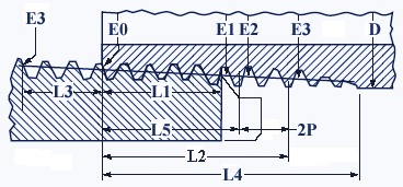
National Standard Taper Pipe Threads Size NPT Chart | ||||||||
---|---|---|---|---|---|---|---|---|
Outside Diameter D |
Nominal Pipe Size |
Threads per Inch (Pitch) |
Thread Pitch Length, P |
Pitch Diameter at External Thread Start E0 |
Hand Tight Thread Engagement
Length, L1 |
Diameter E1 |
Maximum Thread Engagement L2 |
Diameter E2 |
0.3125 |
1⁄16 |
27 |
0.03704 |
0.27118 |
0.160 |
0.28118 |
0.2611 |
0.28750 |
0.405 |
1⁄8 |
27 |
0.03704 |
0.36351 |
0.1615 |
0.37360 |
0.2639 |
0.38000 |
0.540 |
1⁄4 |
18 |
0.05556 |
0.47739 |
0.2278 |
0.49163 |
0.4018 |
0.50250 |
0.675 |
3⁄8 |
18 |
0.05556 |
0.61201 |
0.240 |
0.62701 |
0.4078 |
0.63750 |
0.840 |
1⁄2 |
14 |
0.07143 |
0.75843 |
0.320 |
0.77843 |
0.5337 |
0.79179 |
1.050 |
3⁄4 |
14 |
0.07143 |
0.96768 |
0.339 |
0.98887 |
0.5457 |
1.00179 |
1.315 |
1 |
11 1⁄2 |
0.08696 |
1.21363 |
0.400 |
1.23863 |
0.6828 |
1.25630 |
1.660 |
1 1⁄4 |
11 1⁄2 |
0.08696 |
1.55713 |
0.420 |
1.58338 |
0.7068 |
1.60130 |
1.900 |
1 1⁄2 |
11 1⁄2 |
0.08696 |
1.79609 |
0.420 |
1.82234 |
0.7235 |
1.84130 |
2.375 |
2 |
11 1⁄2 |
0.08696 |
2.26902 |
0.436 |
2.29627 |
0.7565 |
2.31630 |
2.875 |
2 1⁄2 |
8 |
0.12500 |
2.71953 |
0.682 |
2.76216 |
1.1375 |
2.79062 |
3.500 |
3 |
8 |
0.12500 |
3.34062 |
0.766 |
3.38850 |
1.2000 |
3.41562 |
4.000 |
3 1⁄2 |
8 |
0.12500 |
3.83750 |
0.821 |
3.88881 |
1.2500 |
3.91562 |
4.500 |
4 |
8 |
0.12500 |
4.33438 |
0.844 |
4.38712 |
1.3000 |
4.41562 |
5.563 |
5 |
8 |
0.12500 |
5.39073 |
0.937 |
5.44929 |
1.4063 |
5.47862 |
6.625 |
6 |
8 |
0.12500 |
6.44609 |
0.958 |
6.50597 |
1.5125 |
6.54062 |
8.625 |
8 |
8 |
0.12500 |
8.43359 |
1.063 |
8.50003 |
1.7125 |
8.54062 |
10.750 |
10 |
8 |
0.12500 |
10.54531 |
1.210 |
10.62094 |
1.9250 |
10.66562 |
12.750 |
12 |
8 |
0.12500 |
12.53281 |
1.360 |
12.61781 |
2.1250 |
12.66562 |
14.000 |
14 |
8 |
0.12500 |
13.77500 |
1.562 |
13.87262 |
2.2500 |
13.91562 |
16.000 |
16 |
8 |
0.12500 |
15.76250 |
1.812 |
15.87575 |
2.4500 |
15.91562 |
18.000 |
18 |
8 |
0.12500 |
17.75000 |
2.000 |
17.87500 |
2.6500 |
17.91562 |
20.000 |
20 |
8 |
0.12500 |
19.73750 |
2.125 |
19.87031 |
2.8500 |
19.91562 |
24.000 |
24 |
8 |
0.12500 |
23.71250 |
2.375 |
23.86094 |
3.2500 |
23.91562 |
Pneumatic Parts Reference | |||||||||||||
---|---|---|---|---|---|---|---|---|---|---|---|---|---|
|
|